Nanite Tree Pipeline

1Cloud Imperium Games, 2Tencent Games

Left Tree is generated after our Nanite Tree Pipeline, rendered with Opaque leaf material. Right Tree is created using traditional manual workflows, rendered with Masked material and leaf mask textures.

Performance: with both tree enabled Nanite & WorldPositionOffset Animation, right tree consumes 2 to 3 times more performance than to the left Tree. Furthermore, when Nanite is disabled, the performance of right tree increases another 3 ms.

Abstract

This is an automated Nanite Tree Tool designed to convert traditional non-Nanite vegetation models into Nanite models suitable for Unreal Engine 5. The core functions of this tool include vertex layout reconstruction, polygon merging, and LOD generation, aiming to simplify the process of vegetation asset creation and improve artistic creation efficiency. Through our tool, artists can quickly convert original billboard models to leaf modeling vegetation models suitable for Nanite rendering, achieving higher-quality rendering effects and better performance.

Interpolation end reference image.

Details of NaniteTreePipeline has been revealed at the 2023 UE Fest speech

Pipeline Overview

Interpolation end reference image.

In addition to providing automated asset conversion functions, this tool also allows artists to fine-tune parameters as needed to optimize the final rendering effects. By validating the impact of each modification on the final effect in the engine, artists can achieve satisfactory rendering results faster.

As an open-source project, this tool provides a reliable solution for the vegetation creation process in Unreal Engine 5 and contributes a practical technical tool to the game development community. Through open-source, we hope to inspire more developers to participate and collectively drive technological advancement and creative efficiency in the gaming industry.

How to build your own hda tool

In the previous version, the output consistently produced incorrect leaves. This was due to the [END_LOOP_Leaf] node toggling [single pass], which caused the loop to step in a single plane and generate only one leaf. As a result, all subsequent processes yielded incorrect outcomes.

Interpolation end reference image.

When using, you must first determine the following information of the input model [Model name (name that affects the output) [Material name of the trunk] [Material name of the leaves] (This material name is the material slot name)

Interpolation end reference image.

You can modify the code here, mainly to control the buttons

Interpolation end reference image.

What kind of projects are suitable for NaniteTree Pipeline?

Interpolation end reference image.


Interpolation end reference image.

Overview of Asset Export to Unreal

Automatically recognize tree trunks , leaves and LODs , UCX based on input rules.

Houdini

Using with HDK & Python


Enter the model file and set the corresponding rule parameters (such as the leaf material name of your model, this will be used to identify and distinguish the leaf part from the trunk part)


Unreal Plugin

Using with HDA


Enter the model file and set the corresponding rule parameters (such as the leaf material name of your model, this will be used to identify and distinguish the leaf part from the trunk part)


Interpolation end reference image.

Effect Contrast

Leaves Mesh Generation


Enter the model file and set the corresponding rule parameters (such as the leaf material name of your model, this will be used to identify and distinguish the leaf part from the trunk part)


HDA Preview

Nanite virtual Geometry Technology

GPU-Driven Pipeline


“GPU-Driven” is also a well-discussed topic. In the traditional Vertex-Raster-Pixel Shading pipeline execution process, the GPU front end, after processing instructions from the Host Interface, has the Primitive Distributor distribute mesh information in batches from the Index Buffer to various GPCs (in the case of Nvidia GPUs). Within the SM unit, the PolyMorph Engine takes on responsibilities such as Vertex Fetch, Tessellation, Viewport Transform, Attributes Setup, and Stream Out, connecting the rendering pipeline’s upstream and downstream segments. Under the guidance of the Warp Scheduler, thread bundles complete Vertex calculations, then pack the data to the Raster Engine for hardware rasterization. The processed data is then sent back to the SM unit for Pixel stage shading and ultimately output by the ROP. The entire process is seamless, and apart from the programmable parts in the GPU stages, there is limited control. The remaining logic computations and organizational aspects are predominantly handled by the CPU.

On one hand, the increasing pressure on the CPU makes it desirable for the GPU to assist in computations beyond rendering. On the other hand, there is a desire for even more precise culling than at the Object or Instance level. Given the compactness of the aforementioned pipeline, it is necessary to find an executor for this work outside the traditional rendering pipeline, and currently, the only option seems to be the Compute Shader! With capable hands on deck, the next step is to address one crucial aspect: how the GPU independently tackles computation, decision-making, and most importantly, the DrawCall problem. Thanks to certain features of new versions of Graphics APIs, such as Indirect Draw, some tasks that were originally entirely CPU-implemented can be delegated to the GPU for computation and data read/write operations. This approach not only reduces the communication latency between GPU and CPU but also maximizes the GPU’s parallel computing capabilities to further refine culling granularity, thus reducing OverDraw in the rendering pipeline. This is the essence of the GPU-Driven approach.

In this field, some projects provide valuable engineering references, such as Ubisoft’s presentation on “GPU-Driven Rendering Pipelines” at SIGGRAPH 2015 [1], where they discussed various GPU-based culling techniques, including Cluster-based culling and the support of Virtual Texture throughout the GPU-driven pipeline. They introduced an intriguing concept called “Single Draw Call Rendering,” where an entire scene is rendered with a single Draw Call. Although somewhat idealized, it indeed significantly improves overall performance. Following this, at GDC 2016, EA’s Frostbite Engine presented their GPU-Driven solution in “Optimizing the Graphics Pipeline with Compute” [2]. In the subsequent years, Ubisoft continued to share GPU-Driven rendering solutions in 2018 and 2019 at GDC. These included the terrain rendering approach in “Far Cry 5” [3] and “GPU Driven Rendering and Virtual Textureing in Trials Rising” [4]. Unreal Engine 4 (UE4) also designed its GPU-Driven solution in earlier versions, and these technological foundations have now been employed as part of the Nanite framework. Essentially, the entire Nanite framework is built upon GPU-Driven principles.


Interpolation end reference image.


Interpolation end reference image.

Hardware & Software rasterization


Nanite employs a hybrid rasterization strategy, addressing the fundamental question of when hardware rasterization is appropriate versus when software rasterization is more suitable. Hardware rasterization typically involves two steps: Coarse Rasterization at an 8x8 pixel block level and Fine Rasterization at a 2x2 pixel block level. During Coarse Rasterization, obscured blocks are culled using a low-resolution Z-Buffer, leaving only the visible areas for shading. Then, Fine Rasterization operates at a 2x2 pixel block level (Pixel Quad) to perform the final rasterization output. This design choice, with blocks of 2x2 pixels, enables access to neighboring pixel information for executing DDX, DDY operations to facilitate hardware-level MIP calculations. The historical rationale behind this design stems from early days when most triangles were significantly larger than a single pixel. Compared to the extensive fetch of vertex attributes, texture sampling, and numerous shading calculations, hardware rasterization incurred relatively low overhead in the rendering pipeline, making it highly efficient for most scenarios. However, this “one-size-fits-most” approach occasionally leads to significant inefficiencies, especially when scenes contain a high density of triangles, with many triangles occupying less than a single pixel. In such cases, the coarse culling in Coarse Rasterization becomes largely ineffective, and Fine Rasterization faces substantial waste. For instance, a small triangle spanning three Pixel Quads may realistically cover only three pixels, but the 2x2 Quad mechanism would process all twelve pixels, resulting in considerable computational overhead. In scenarios like these, where triangles densely populate the viewport and many occupy less than a single pixel, software rasterization can be more efficient. Coupled with GPU-Driven techniques, Cluster or Meshlet-level culling further narrows down the triangle range for rasterization. Most importantly, the entire system seamlessly integrates into a unified pipeline.


Interpolation end reference image.

MeshShader


Nvidia unveiled its proprietary Mesh Shader pipeline at SIGGRAPH 2019 [5], taking GPU-Driven approaches directly to the hardware level in a single leap. The rationale behind this advancement lies in addressing the potential “inefficiency” risk associated with traditional GPU-Driven methods, primarily stemming from the historical baggage of the rasterization pipeline’s execution flow. Without considering technologies like Virtual Texturing (VT), GPU-Driven solutions primarily tackle culling issues. If a target triangle is successfully culled, it’s advantageous. However, if not, it involves a convoluted process of data storage, computation, register writing, and subsequent reading. This is because, without considering software rasterization, the triangle ultimately needs to return to the original rendering pipeline, undergoing another Vertex Fetch process. Before Vertex Fetch, there are fixed pipelines like Primitive Distributor that cannot be bypassed. Nvidia’s solution involves a radical departure by discarding the traditional Vertex Shader (VS), Tessellation, and Geometry stages. Instead, they establish a new paradigm where Meshlets, after collaborative thread group computations for culling, seamlessly interface with the hardware rasterizer. This streamlined approach ensures a more efficient and direct integration of GPU-Driven techniques into the hardware pipeline.

In this setup, the Task Shader essentially takes on the role of culling previously handled by Compute Shaders (CS), while the Mesh Shader itself assumes responsibility for geometric topology. However, it’s notable that Nanite is not based on Mesh Shader technology. The question arises: Why? One speculation is that Mesh Shaders might not directly address the challenge of handling vast numbers of small triangles. Additionally, the current high hardware costs for users adopting Mesh Shader technology could hinder its widespread adoption. Therefore, a more conservative approach utilizing Compute Shaders for GPU-Driven techniques and a hybrid rasterization scheme might be preferable. According to official statements, Nanite’s innovation lies in LOD (Level of Detail) construction and Culling, areas that have been the focal points of technical showcase by major game developers over the past decade.

Interpolation end reference image.

Nanite Detailed Analysis


Currently, there aren’t many articles analyzing Nanite. Official resources primarily include Brian Karis’s presentation “Nanite: A Deep Dive” at SIGGRAPH 2021 [6]and Wang Mi’s “Development Roadmap and Technical Analysis of Unreal Engine 5” [7].Regarding unofficial sources, four articles stand out for their quality technical insights [8],[9],[10],[11]. Additionally, analysis is supplemented by examining the latest 5.0.3 source code. Nanite’s comprehensive implementation involves a wealth of engineering expertise across various domains, including GPU-Driven techniques, software rasterization, geometric modeling, BMT processing, and data compression. What is particularly commendable is the integration of these diverse components into the already intricate Deferred rendering framework while ensuring both sufficient performance and transparency to the upper-level design processes. Transparency, in this context, means that alterations in the underlying architecture do not disrupt the users’ accustomed operations and development workflows. Achieving this demands not only extensive knowledge in graphics development but also seasoned engine engineering skills. Furthermore, it necessitates immense courage and, perhaps, a touch of audacity to undertake such a monumental task. Achieving this goal sounds a bit outlandish, but then again, it’s Brian Karis, so it’s somewhat expected. Macroscopically, the rendering pipeline steps of Nanite appear as illustrated in the diagram on the right.


Interpolation end reference image.

Cluster Building Stage


The entire mesh is divided into clusters, each consisting of 128 triangles, following the “Lowest Contribution Boundary” and “As Uniform Area as Possible” partitioning strategy between clusters. This ensures minimal errors in subsequent simplification processes. The logic for LOD construction is as follows: Initially, 32 to 64 clusters form a Cluster Group. A crucial step in this process is the Lock Edge operation performed on the Cluster Group, which is fundamental to ensuring a well-structured partition. Subsequently, triangles within the group undergo a merging process, gradually eliminating internal boundaries without affecting the group’s perimeter. This step employs a dedicated triangle simplifier using the QEM (Quadratic Error Metric) simplification algorithm. This yields a LOD1-level Cluster Group. The next step involves performing splits within the LOD1-level Cluster Group, effectively re-partitioning the triangles.

From the simplification diagram above each cluster represented by 4 triangles for illustration, it can be observed that the boundaries and shapes of the triangles generated after simplification are no longer related to the original LOD level. The simplification process is not a crude “merge” or “collapse” of triangles; instead, the outer boundaries of the entire group are locked. The simplification process adheres to the strategy of “Lowest Contribution Boundary” and “As Uniform Area as Possible,” ensuring that each simplification maintains consistent area proportions and coverage between the “triangular strips.” This minimizes projection errors and enhances texture mapping precision.

Each iteration follows the aforementioned principles, and after each generation of a new LOD through Grouping, Merging, Simplification, and Splitting, the errors for each Cluster and Group are recorded. These errors, along with the errors from the next iteration, are used to calculate the maximum error metric (Max Error Metric). This results in a LOD tree where errors are in descending order with an increase in face count. This enables subsequent comparisons of screen projection ratios and errors to dynamically select the appropriate LOD level. The iterator generates a tree structure with a root node containing only one Cluster, and a BVH (Bounding Volume Hierarchy) is built based on this structure to accelerate GPU-Driven Culling. The entire process is parallelized. After BVH construction, a paged data storage model is established on a Cluster Group basis, with each page being 128kb. A constraint is imposed that only Cluster Groups that are spatially adjacent and belong to the same LOD are placed in the same page. To ensure spatial adjacency and data layout continuity, “Morton 3D” is employed. Notably, the vertex information held by the Nanite Mesh is minimal, potentially lacking data such as Vertex Tangents. Tangent data is calculated in real-time based on existing point attributes, following two principles: first, eliminate data that can be calculated to save storage, I/O pressure, and index calculations; second, minimize the bit count for mandatory attributes. After the completion of the Nanite Mesh construction process, a crucial step is data compression. Given the large number of vertices and the need for a global Vertex Buffer for efficient real-time streaming operations, data compression is essential. The specific compression algorithm is yet to be determined, but it involves a trade-off between precision loss and performance. Epic Games undoubtedly aims to strike the optimal balance.


Interpolation end reference image.


Interpolation end reference image.

Culling Stage


Culling in Nanite is entirely GPU-driven. The process includes View Frustum Culling and Hierarchical Z-Buffer (HZB) culling. Backface Culling and Small Triangle Culling are not performed at this stage. There are three levels of culling. First is at the Instance level, which is the granularity achievable by traditional rendering pipelines. Next, after Instance culling, the Mesh undergoes BVH (Bounding Volume Hierarchy) Node Culling, which is hierarchical and dynamic. Ensuring load balancing across Compute Shader (CS) thread groups is crucial, ensuring that each thread is fully utilized without idling. Due to potentially significant differences in BVH depth for each Mesh, it’s inappropriate to allocate thread groups based on Cluster leaf nodes. In UE5, a global First-In-First-Out (FIFO) queue is maintained to retrieve BVH nodes. If a node passes culling, all its child nodes are moved to the end of the queue. This process continues until the global queue is empty. This approach ensures that the processing time is roughly equal among threads. Nodes that pass are further subjected to Cluster-level culling, and after three levels of culling, the retained triangle faces exhibit significantly reduced waste compared to traditional pipelines.

In reality, the entire culling process consists of two passes: the Main Pass and the Post Pass. From the diagram, these two passes share similar logic, with the difference lying in the fact that the occlusion culling in the Main Pass is based on data from the previous frame, whereas the Post Pass utilizes the Hierarchical Z-Buffer (HZB) constructed at the end of the Main Pass for the current frame. The primary purpose of these two passes is to enhance the accuracy of culling. Additionally, during the Cluster culling stage, triangles are marked to determine whether they will undergo software rasterization or hardware rasterization, depending on their size.


Interpolation end reference image.

Culling Stage


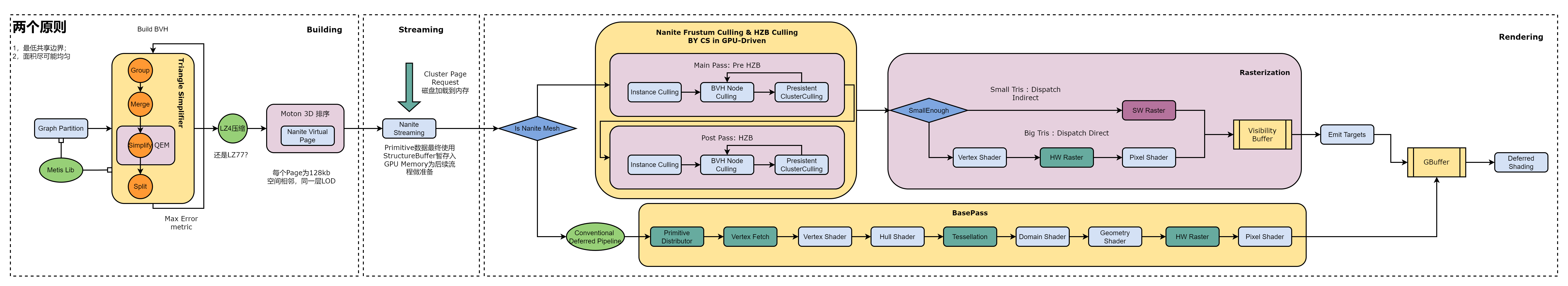
The Visibility Buffer can achieve storage with fewer index details, typically involving InstanceID, PrimitiveID, MaterialID, and Depth. As it stores index information, its volume is inherently smaller than that of the G-Buffer. However, it requires maintaining a global set of Vertex Attributes and a Material Map. In the Shading stage, the process involves indexing relevant triangle information from the global Vertex Buffer based on InstanceID and PrimitiveID. Pixel-wise information is then interpolated based on barycentric coordinates. Material information is obtained from MaterialID, and together they enter the lighting calculation process to achieve the final shading. This process, to some extent, allows for the separation of geometric and shading calculations, a feat not achievable in traditional Deferred rendering, where G-Buffer serves as the bridge between geometry and shading.

In the Nanite workflow, the format of the Visibility Buffer is R32G32_UNIT, where R’s 0-6 bits store Triangle ID, 7-31 bits store Cluster ID, and G contains 32-bit Depth information. Considering the Deferred architecture of the UE4 era, on the one hand, Nanite currently cannot support all types of rendering, and some meshes still need to be rendered using the traditional rendering pipeline. On the other hand, as mentioned by Karis, a crucial premise of this architectural adjustment is transparency to users. This means that changes in the underlying structure should not impact user-level habits or require relearning the engine, which is crucial. To ensure compatibility between the new and old rendering pipelines, there is an Emit Targets stage to connect Nanite with the traditional deferred rendering approach.

The Emit Targets stage is further divided into EmitDepthTargets and EmitGBuffer phases. Initially, besides the Visibility Buffer, shading requires additional data to blend with hard rasterization data. Nanite employs several full-screen passes to write information outside the Visibility Buffer (such as Velocity, Stencil, Nanite Mask, MaterialID) into a unified buffer, preparing for the subsequent GBuffer reconstruction. Specifically, Emit Scene Depth writes the Depth from the Visibility Buffer into the Scene Depth buffer, Emit Velocity writes into the Velocity Buffer, Emit Scene Stencil writes into the Stencil buffer, and Emit Material Depth writes into the Material ID buffer. Regarding the MaterialID Buffer, several strategies are employed, depending on the scene’s material complexity. When there are numerous materials, the screen is divided into 64x64 blocks, and the minimum and maximum values of materials in each block are calculated. This calculation is executed by a full-screen Compute Shader, resulting in an image called Material Range. With this image, in the EmitGbuffer phase, a full-screen draw is triggered for each material, where culling is completed in the Vertex Shader (VS) stage. In the Pixel Shader (PS) stage, shading is applied only to corresponding pixels through Depth Compare, thus outputting information such as Albedo into the GBuffer.


Interpolation end reference image.


Interpolation end reference image.

Related Links

There's a lot of excellent work that was introduced for Nanite Tree Simplification.

Lindstrom-Turk Cost and Placement Strategy introduces edge collapse operation for triangle Simplification.

Garland-Heckbert Cost and Placement Strategy based on iterative edge contraction and quadric error metrics.

Cost Strategy Policies is selected through three strategies: GetPlacement, GetCost and Filter.

SIGGRAPH 2015 ubisoft, GPU-Driven Rendering Pipelines

GDC 2018 Ubisoft, Terrian Rendering in "Far Cry 5"

GDC 2019 Ubisoft, GPU Driven Rendering and Virtual Textureing in "Trials Rising"

Based on Turing architecture GPU Mesh Shader

SIGGRAPH 2021 Epic Games Brian Karis Nanite A Deep Dive

Mi Wang Unreal Engine 5 development roadmap and technical analysis

Jiff UE5 Nanite Brief analysis of implementation

Cheng Luo Introduction to UE Rendering Technology: Nanite

Yue Cong UE5 Nanite source code analysis for rendering: Rasterization

Wang Xiang UE5 Special Part 1: Nanite

Helo Nanite vegetation creation guide in UE5

BibTeX

@article{nanitetree,
  author    = {jiayaozhang,Hikohuang},
  title     = {Nanite Tree Pipeline},
  year      = {2023},
}